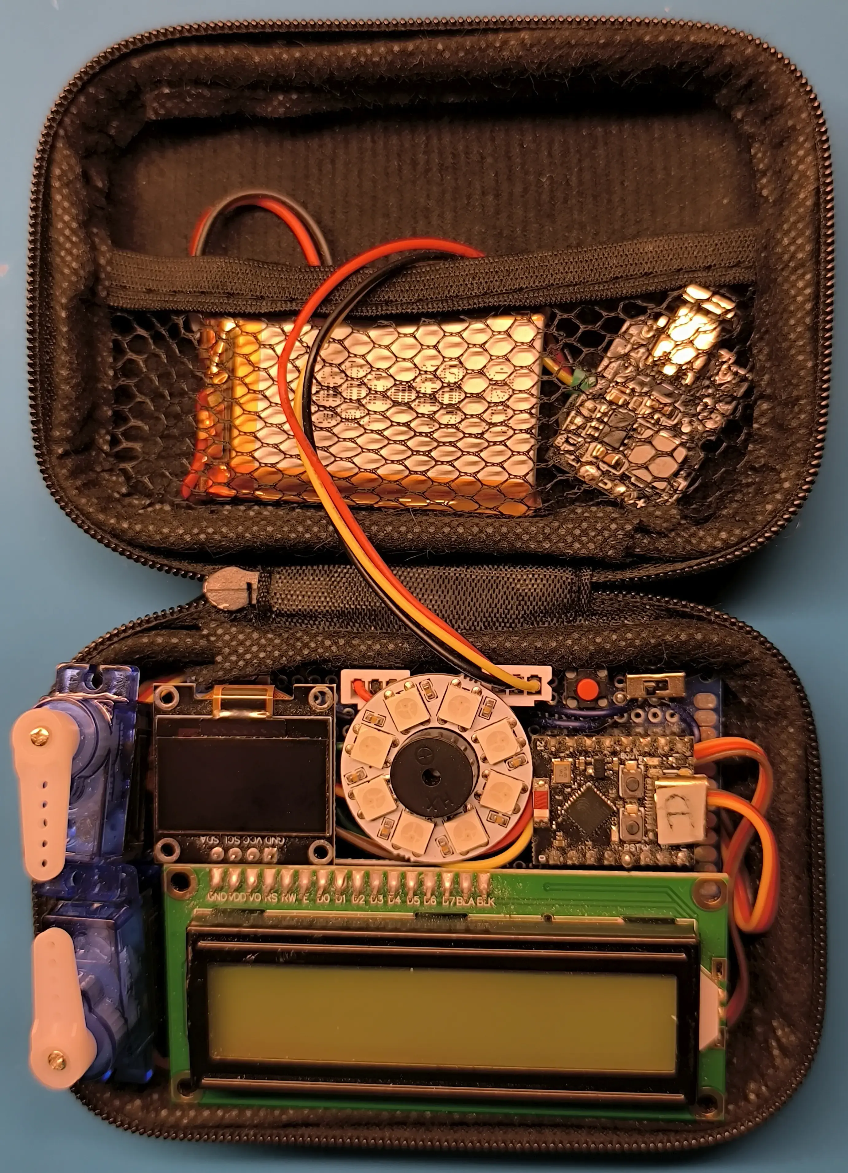
Building the Ravel Kit#
NOTE: click on a photo to view an enlarged version.
Overview of Components#
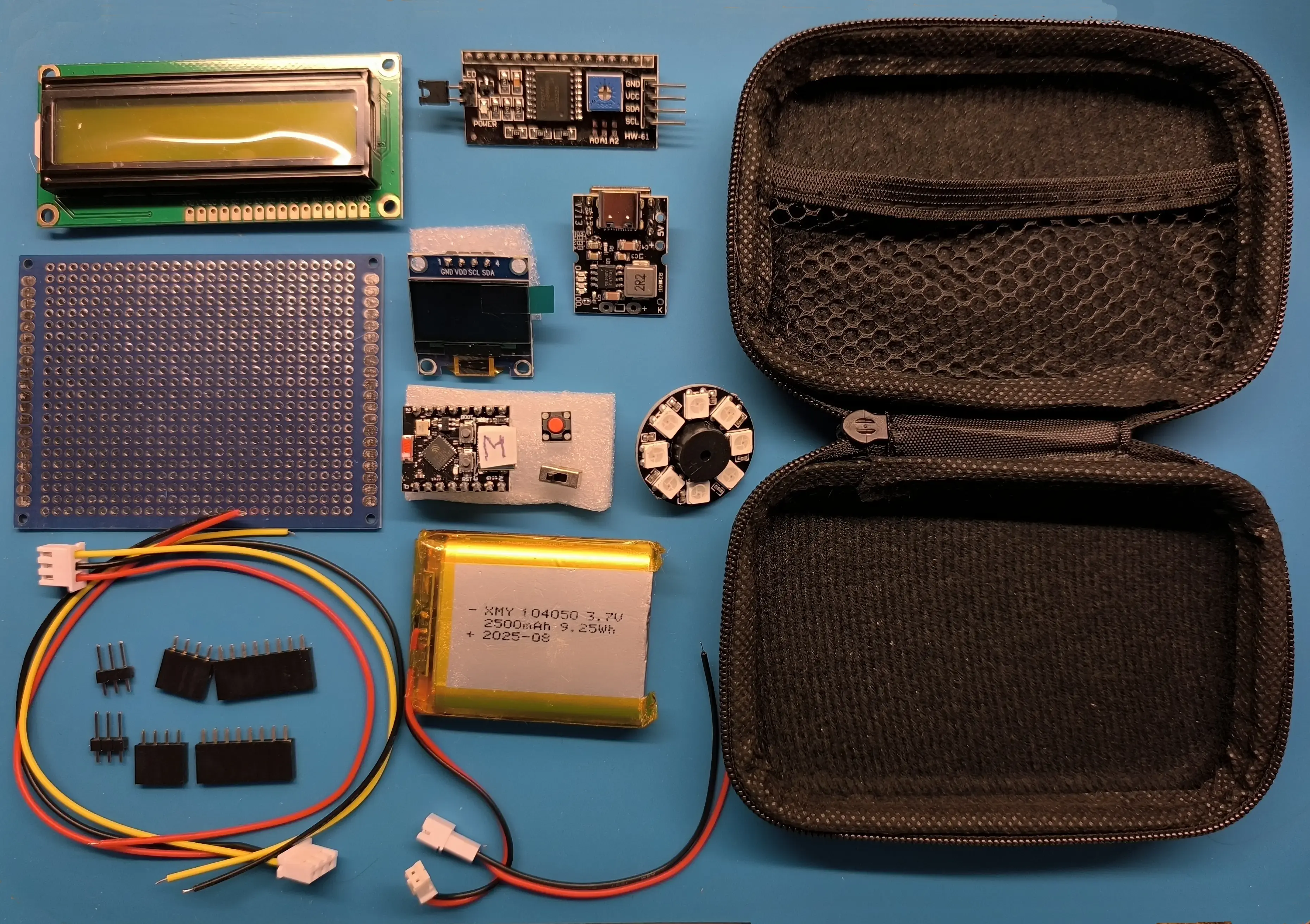
A photo showing almost all the components in the kit. The only ones missing are those related to the servos.
The Microcontroller#
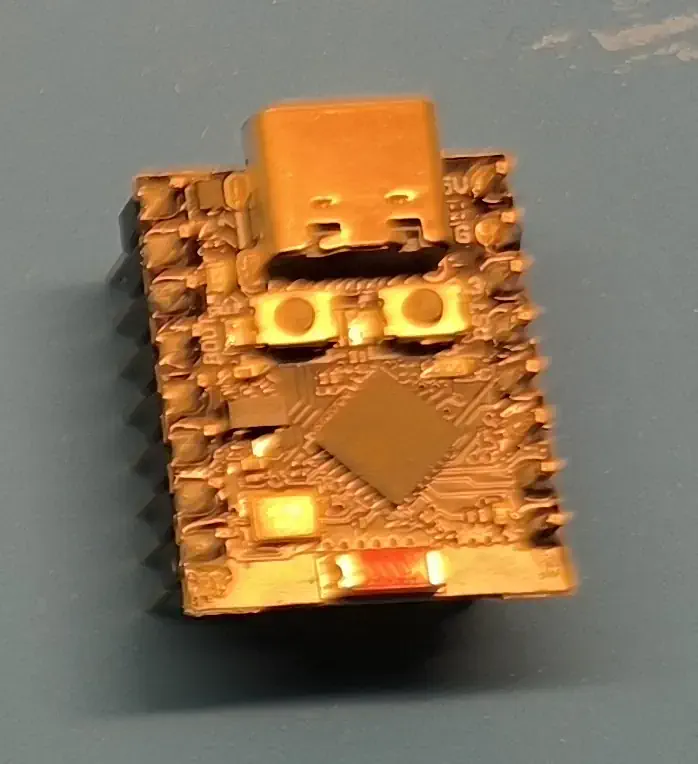
The microcontroller is an ESP32-C3 SuperMini.
The Buzzer#
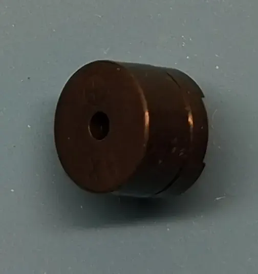
The buzzer is a passive buzzer, meaning you can adjust the frequency of the sound it emits, unlike an active buzzer. It is driven by a PWM signal. Additionally, you can influence the pitch and volume of the sound to some extent by adjusting the PWM signal ratio.
The RGB Ring#
The ring used consists of 8 WS2812 RGB LEDs. Note: There are two sizes, as shown below:
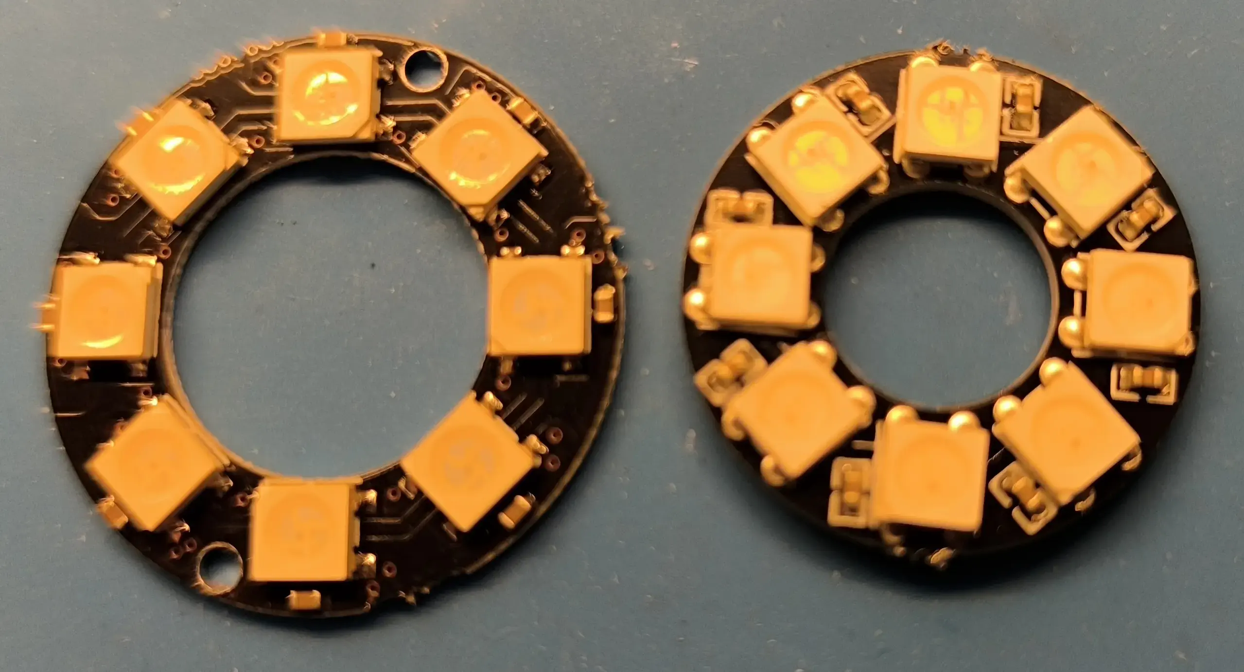
The smaller one has the advantage of having an inner diameter that matches the diameter of a buzzer perfectly. This means we can slide the ring onto the buzzer and secure it by wedging it slightly against the ESP32.
The ring usually comes soldered with two cables (top of the photo). These two cables are too long and too stiff to be used with this kit. The output cable, which is used to connect another ring, is also unnecessary. You should therefore desolder them and replace the input cable with a different model (bottom of the photo).
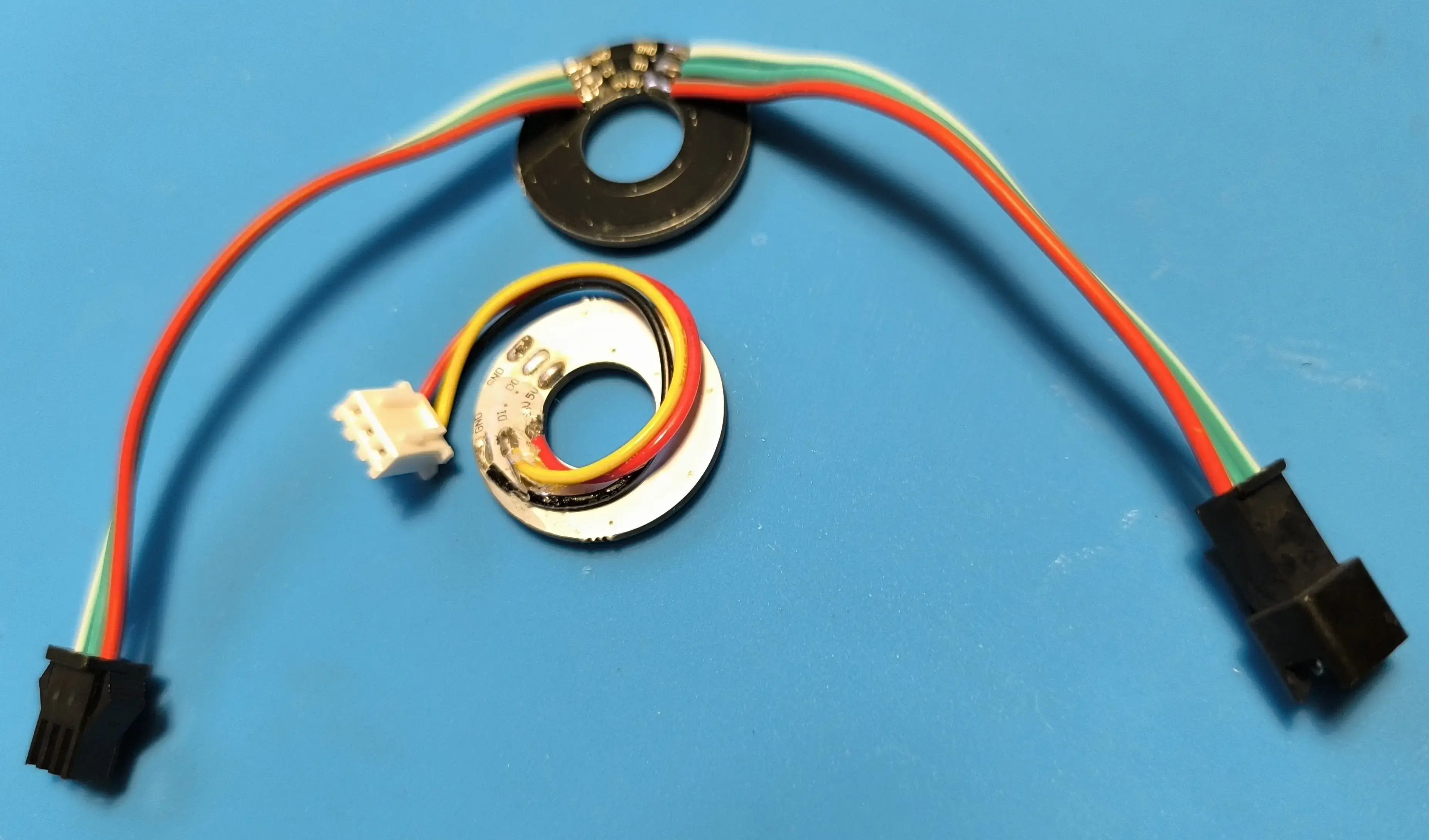
The cable is secured with UV resin to minimize the risk of breakage during handling.
Each color (RGB) can take a value from 0 to 255, but only the lowest values are useful because, the higher the values, the smaller the perceived difference in brightness between two consecutive values. Ultimately, for this kit, only values from 0 to 31, inclusive, are used.
The OLED Display#
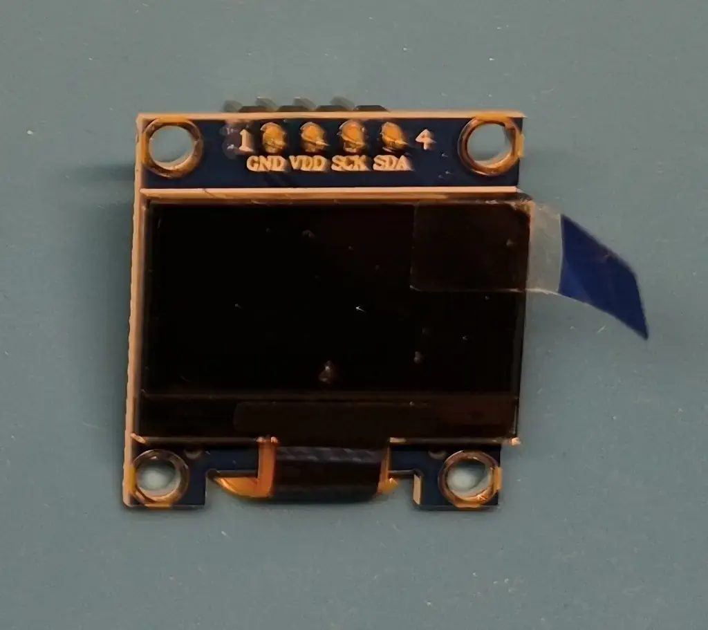
This is an SSD1106, measuring 0.96 inches with a resolution of 128 by 64. It is controlled via I2C.
The LCD Display#
This is a 1602 LCD display with 2 lines of 16 characters each. It is available in several display colors, such as black on a green background or white on a blue background…
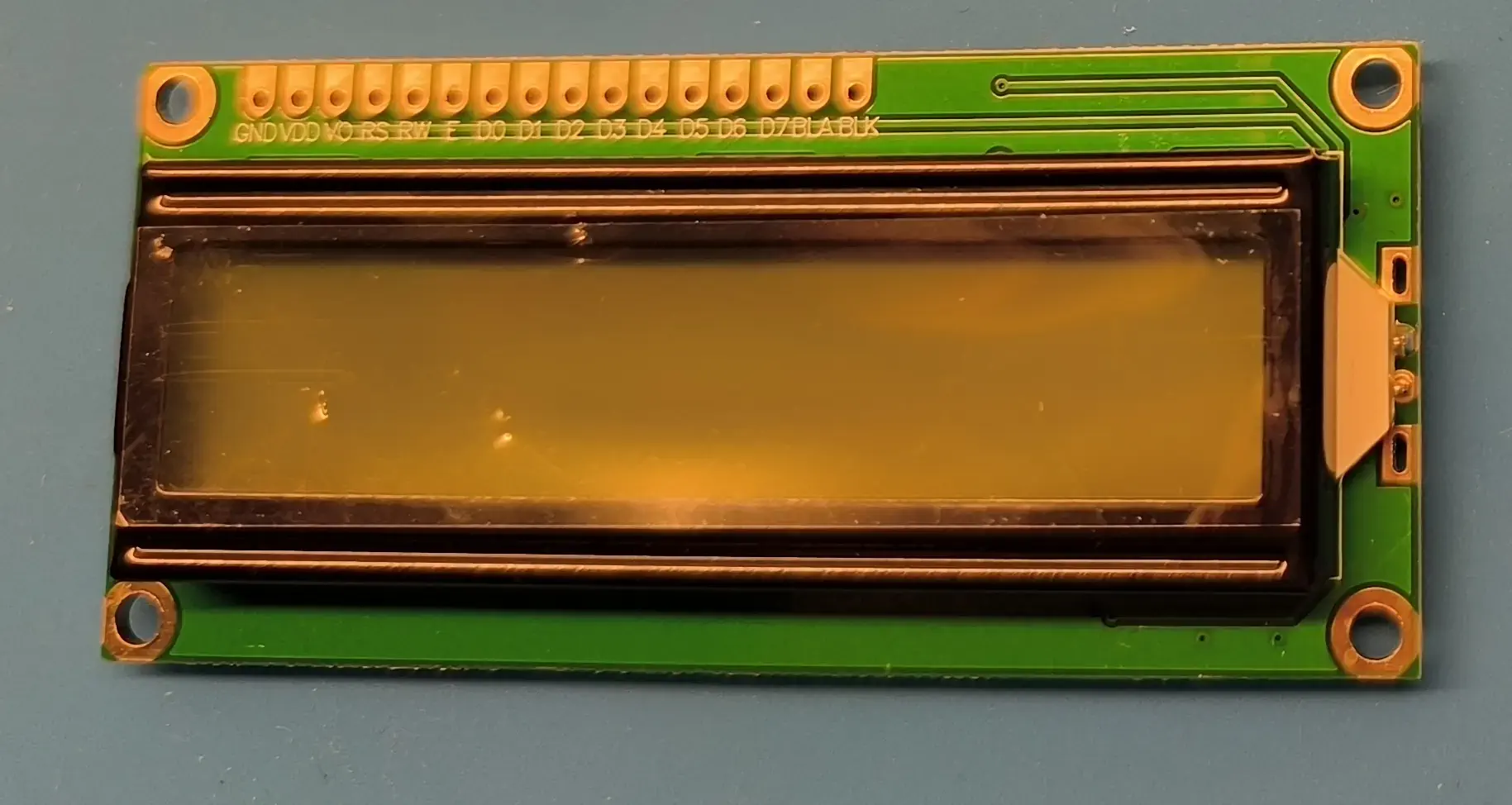
It is paired with a PCF8574, which allows it to be controlled using I2C. This component is not mounted on a socket to save space. Its pins are straightened (at the bottom in the photo) and soldered directly onto the PCB.
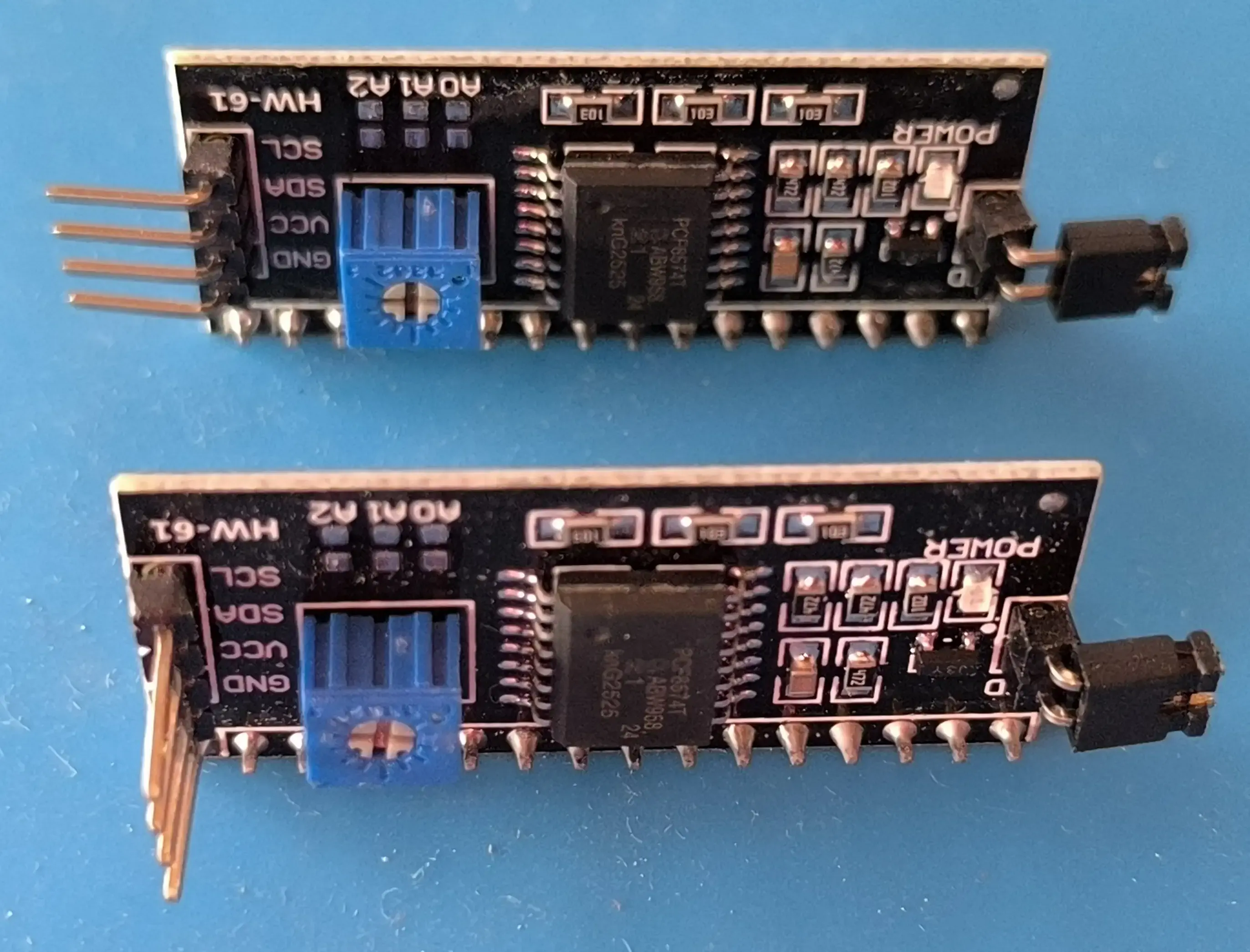
To adjust the display’s contrast after the component has been soldered, you must drill a hole in the PCB at the location of the PCF8574 module’s potentiometer.
Servomotors#
The 180° SG90 servomotors used have an operating voltage range that supports 5V.
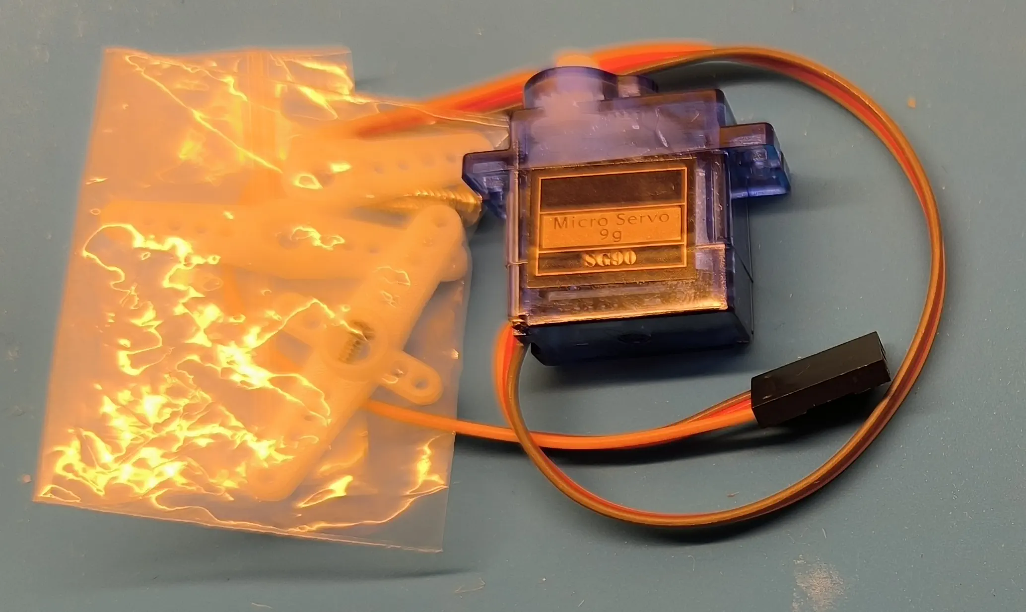
These servomotors can cause current spikes that lead to voltage drops, which in turn can shut down the kit or cause the microcontroller to reboot. To prevent this, a 2200µF/10V electrolytic capacitor is placed between the 5V and GND. This capacitor has a diameter of 1 cm, allowing it to fit under the LCD display. Capacitors larger than 2200µF and/or 16V are less practical for this kit due to their minimum diameter of 13 mm.
The Booster#
The booster is a CKCS 5V2A that takes the 3.7 V from the Li-Po battery as input and outputs 5V (2A). The model used also has a K input that allows you to control the kit’s power on/off. This booster is equipped with a USB-C port that allows you to recharge the battery. Optionally, there is a USB-A port (not visible in the photo, as it is located underneath the booster) that can be used as a power source.
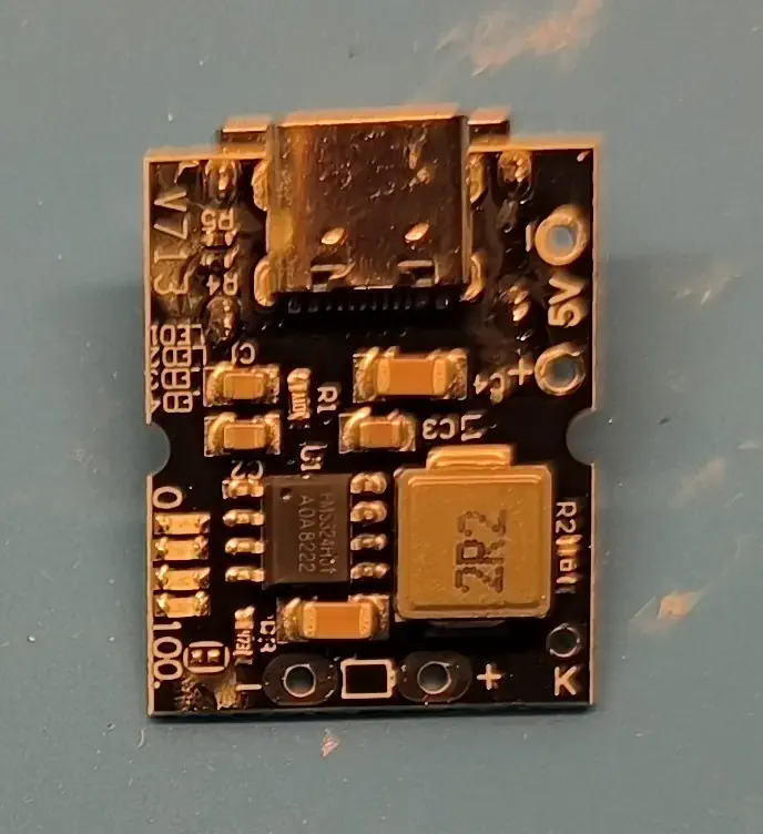
Here too, the cables are secured with UV resin.
Other Components#
A few other components that are also used.
The 3.7 V, 2500 mAh Li-Po battery. It easily lasts several days.
The pushbutton (a mouse button is used here due to its small size and durability), which is placed between the booster’s K input and GND. Pressing it once powers on the kit; pressing it twice powers it off.
The toggle switch, which is connected to the booster’s 5V output, before the capacitor. This prevents the kit from remaining powered while the battery is charging.
An 8x6 cm universal PCB.
A case for Uno cards.
For reference, AWG26 single-strand wire was used to connect the various components.
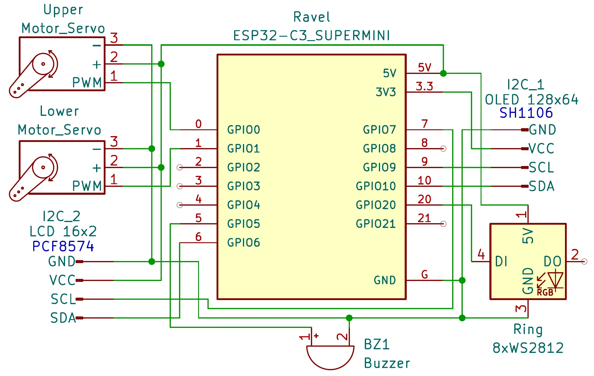
Schematic#
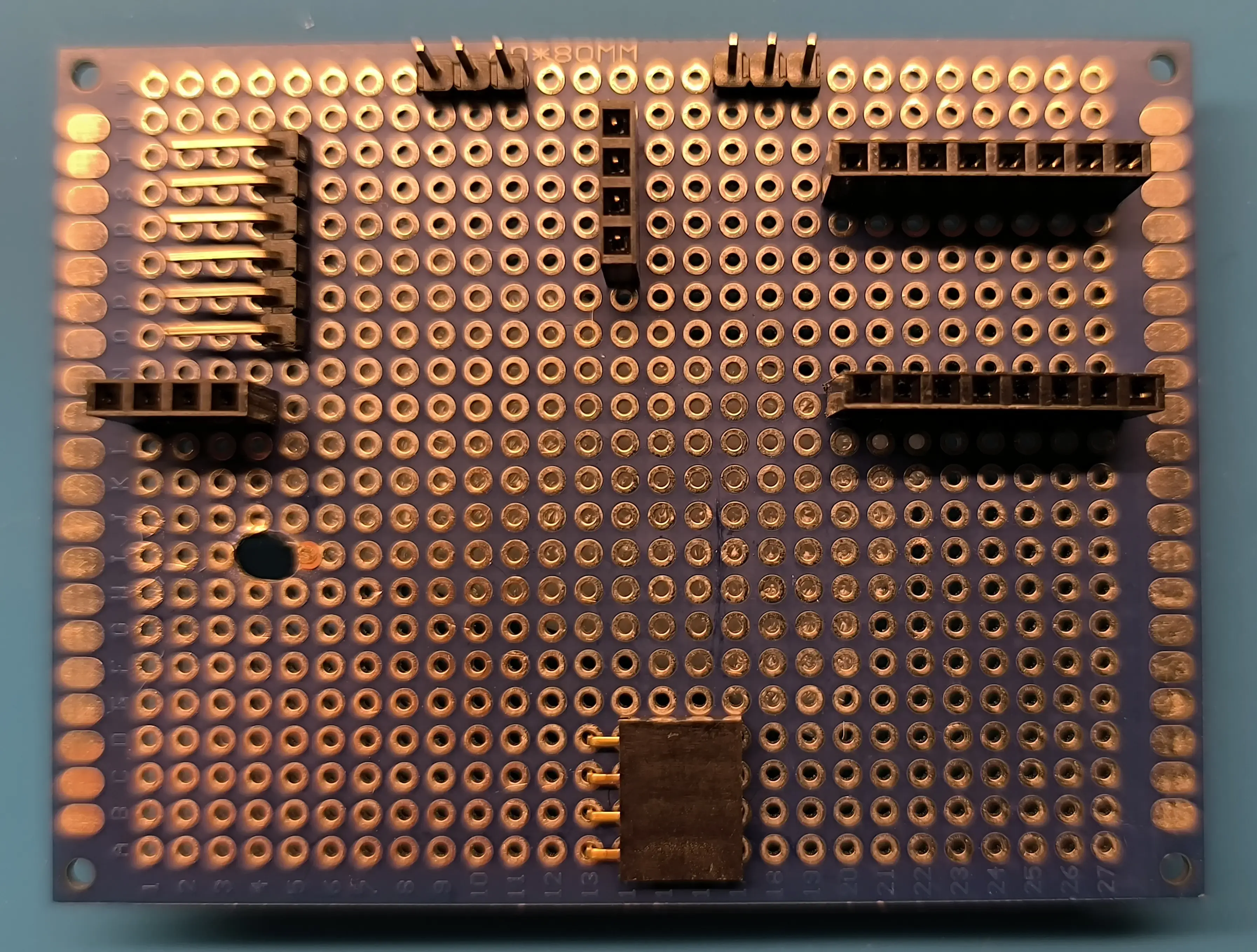
PCB with Sockets#
One can see the opening to access the contrast adjustment potentiometer of the PCF8574.
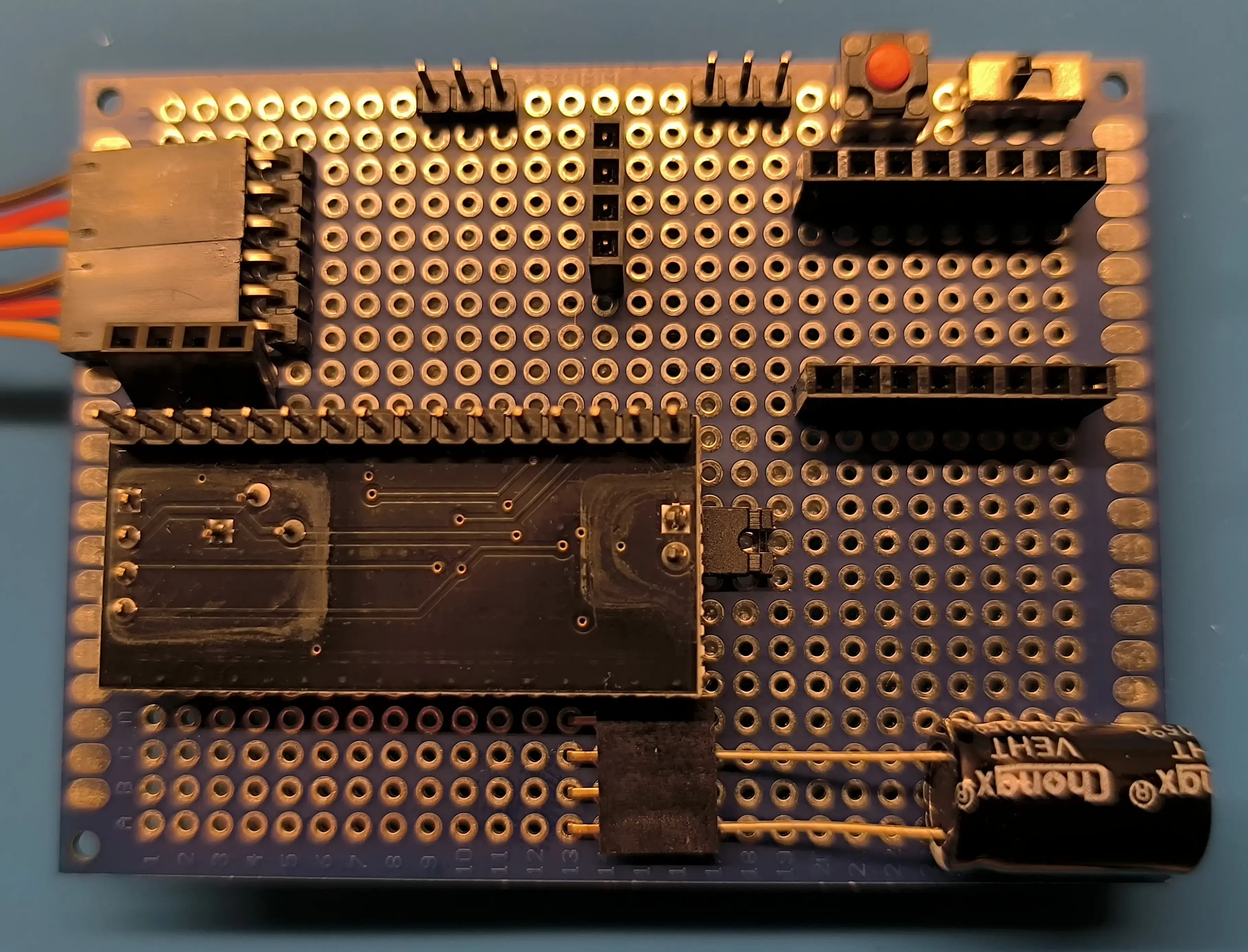
PCB with sockets, hidden components, and soldered components#
The servomotor connector and the capacitor will be hidden by the OLED screen and the LCD display, respectively, once all components are in place. The PCF8574, pushbutton, and toggle switch are soldered directly onto the PCB.
Complete Kit#